Cutting speed
Cutting speed calculation formula and practical applications in programming
INSIGHT
As we have heard in the lessons dedicated to this subject, the cutting speed is a technological datum of absolute importance. In fact, it is the most important piece of information regarding the life of the cutting edge because, as studies and Taylor’s law have shown, a 20% increase in speed corresponds to a halving of cutting edge life. We have also learned the relative mathematical formula and seen how to go from the cutting speed to the number of revolutions using its inverse.
Formulas
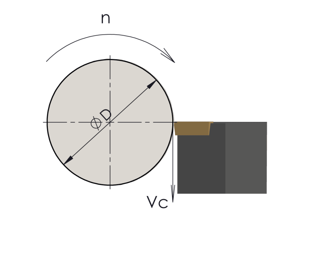
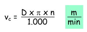
Let’s review the formula for calculating the cutting speed.
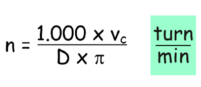
The inverse of this gives the formula for finding the number of revolutions at a given diameter at a given cutting speed.
Calculation examples
Let’s take a look at some practical examples of the use of these two formulas; let’s start with the latter, i.e. the formula for calculating the number of revolutions, and of the two we could say that for a programmer and operator it is also the most widely used. In fact, the first formula, the one for calculating the cutting speed, is less used and the reason is very simple: usually the cutting speed is the value we already know, because it is the value we have to choose according to the tool material and the material to be machined.
This is the value that we have to make our own with experience, with the tables of the toolmakers and that we will refine with the indications in this lesson and the following ones.
A turner on CNC machines will only be required to calculate the number of revolutions in certain very specific applications. The reason for this is that on CNC machines, all turning machines provide for direct programmed input of the cutting speed. The ISO instruction that defines this type of setting corresponds to function G96.
If you type in G96S180, for example, you are setting up a machining process with a constant cutting speed of 180 m/min. The numerical control will at all times read the diametrical position assumed by the tool and calculate the number of revolutions to which the spindle must be brought in order to maintain a constant cutting speed of 180 m/min. This process will be continuous and linked to each diametrical shift performed by the tool, basically the numerical control will apply the second formula for us at every instant.
An operation carried out on a CNC lathe where you have to calculate the number of revolutions because you are working at constant revolutions (ISO G97 function) is, for example, drilling.
So let’s take a practical example with concrete numbers that may also be reliable.
Practical example
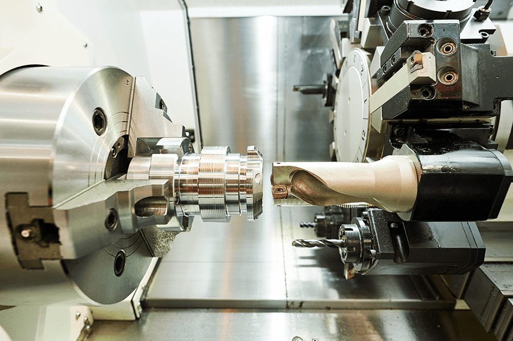
I have to drill a hole in the centre of the workpiece with a d.45 insert drill on a piece of weakly alloyed steel. We’ll set a cutting speed of 180 m/min. How many revolutions should we set for the machining?

In the case of ISO-based CNC machines, we will program G97S1273.
I strongly recommend that if you are unfamiliar with maths, you try it again to familiarise yourself with the formula and the numbers themselves.
Let us now try to calculate the cutting speed, and a practical case in turning could be related to the limitation of revolutions.
RPM limitation is a command that those who already work on CNC lathes are certainly familiar with. It is programmed in conjunction with the G96 function and to be precise before the block containing this function. The instruction for Fanuc controls is G50 if set with type A G codes or G92 if set with type B and C codes. Meanwhile, the instruction for SIEMENS 840D and LIMS controls=____
The limitation is a fundamental instruction because it serves to set a limit in the calculation of the number of revolutions carried out by the numerical control during machining at constant cutting speed. In fact, as we have said, the numerical control will calculate the number of rotations for us, and as the diameters become smaller and smaller, it will automatically increase the rotations because in the formula the diameter is inversely proportional to the rotations.
Even in end milling operations, reaching the centre of the workpiece where the diameter is zero, the revolutions will tend towards infinity. From here comes the need, mainly for safety reasons, to set a limit value beyond which it will maintain constant revolutions equal to the limit.
Let’s take a look at the case where we set a constant cutting speed of 180 m/min (G96S180) with a limitation of 1200 rpm. At diameter 20mm we find that the limitation to 1200 rpm has already been applied. We will use the formula for calculating the cutting speed to check at what actual cutting speed the tool is working at diameter 20mm.

Our tool at d.20, working in the rpm limitation zone, will be working with a cutting speed of 75m/min and not the set 180m/min.
How to choose the cutting speed
The cutting speed is selected according to:
- the material to be machined
- its hardness
- its supply conditions
- the grade of cemented carbide to be used for machining
Tougher cemented carbide grades need higher cutting speeds and are more suitable for finishing and semi-finishing operations. Tougher cemented carbide grades are recommended for roughing operations and need more moderate cutting speeds. This is also responsible for the friction and the consequent temperatures generated in the cutting zone. It is these that lead to the development of chemical and physical reactions on the cutting edge of the tool and determine the resulting degree of wear.
It goes without saying that the higher these temperatures, the shorter the life of the cutting edge. But how do toolmakers or builders recommend a certain cutting speed? What aspects are taken into account? What are the conditions under which suggested cutting speeds are tested? Let’s answer all these questions by saying that every builder spends a lot of time, resources and money to be as accurate and reliable as possible when it comes to writing something in their technical manuals.
Having said that, for each family of materials (P, M, K, etc.) a sample part is taken. Specifically ,for the steel family is a C40; for the stainless steel family is an austenitic AISI316; for the cast iron family is a grey cast iron. A hardness of 180HB is also set for the first two families and 220HB for cast iron. Naturally, the condition of the workpieces is excellent: no interrupted cuts, no melting crust and few impurities inside, the tool protrusions are practically none and the machines on which the tests are carried out are modern and practically perfect and in excellent condition.
There is one more thing to remember, which is that the working data written in the catalogues state that the tool life is 15-20 minutes of workpiece contact. The reason for this is that these minutes under these conditions are economically advantageous so that a cutting edge of, for example, a mechanically fixed insert pays for itself.
But can we have similar conditions in our workshop? Can we consider a cutting life of 15-20 minutes? The obvious answer to these questions is often negative. In our workshops, it happens that we work with overhanging tools and vibrations, that we use tools on conventional machines or that we machine harder workpieces than those taken as samples by tool manufacturers.
What to do in these cases?
Clearly, many aspects related to the machine conditions or those of the tools and parameters used will have to be analysed, and with regard to cutting data, the fundamental parameter for cutting life, i.e. cutting speed, should be reviewed.
This is because if, for example, I had to machine a piece of steel that was harder than the sample, I would not be able to blindly trust the parameters written on the labels of the insert boxes, since they were made from workpieces with a shorter life. We also include a conversion table between the various hardness scales which we think it is important to know.
If I wasn’t able to make changes I would see the cutting life compromised in a time no longer satisfactory to my machining.
What then? So at this point we suggest you to use a table similar to the one below:

This table is certainly not intended to be an absolute solution, but it is a valuable aid to the observant and experienced operator and programmer.
Here’s how it works: first of all we notice that this tool is divided into two parts, one dealing with workpieces of higher hardness and one with workpieces of lower hardness. We have indicated the various families of materials P, M and K, the sample materials and their hardness.
In the middle of the table, at the number zero, you can see below a coefficient fixed with the number 1. If you are machining a workpiece with a hardness equal to that of a sample workpiece, you do not have to make any changes, so you can make the value defined by your tool builder, i.e. the one you find behind the insert boxes.
If, on the other hand, your piece of steel has a higher hardness, for example 220HB, you will use the table to find your corrective factor.
Between 180HB of sample hardness and 220HB there is an extra 40HB of variation. So you will move to the right-hand side of the table which concerns workpieces with increased hardness and under the column +40HB you will find a number which is the correction coefficient to be applied to the cutting speed; in this case is 0.84.

Let’s take an example: your builder recommends a cutting speed of 200m/min using the inserts for a steel of 180HB hardness. But you are working with a workpiece that is 40Hb harder than the sample, so you have to multiply the suggested speed by the coefficien; so 200×0.84 to get a 16% lower cutting speed of 168 metres per minute.
With this revised and corrected data you will theoretically still have a cutting duration of 15-20 minutes. Obviously in the opposite case, so when a workpiece has a lower hardness, I will multiply by a coefficient greater than 1. Therefore I will increase the working data relating to the cutting speed in order to have the same cutting time.

