Tool radius compensation
Tool radius compensation functions and RND and RNDM round function
INSIGHT
In today’s lesson we saw the tool radius compensation functions G40, G41, G42 and the RND round programming function. In order to learn the concepts, it is essential to apply them, so in today’s in-depth discussion I will give you some directions for performing the exercise attached to the lesson. You will find both the drawing and the correct program to verify what you have done.
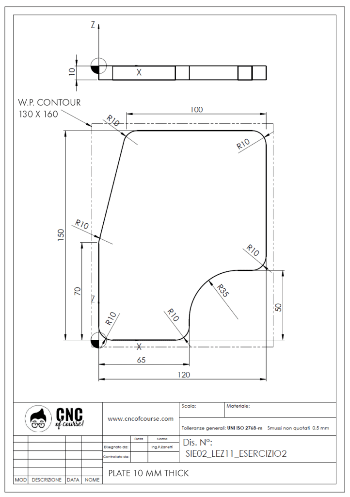
Let’s first analyze the drawing:

We will need to contour the 10mm-thick plate, using the D.63 square shouldered milling tool that we have already configured in the previous exercise, which will then have “SQUARE ENDMILL_D63” as its name.
The workpiece offset will be on the finished edge in the lower left corner and we will use the G54 offset.
Our blank plate is 130×150, thickness 10, and the blank is divided equally on all four sides leaving 5mm of allowance per side. The definition of the bottom left point of our workpiece will therefore have to take into account that the blank is 5mm in the X-direction and 5mm in the Y-direction from our offset. In the Z-direction the blank is already 10mm so the offset in Z is positioned on the surface of the blank.

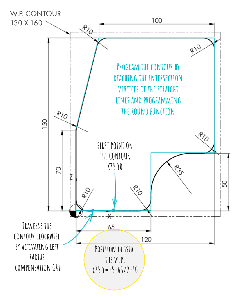
One last thing before I leave you to the exercise and that is about programming the contour; attach the tool radius compensation on a straight side, for example in my program I started from X35 Y0.
Then stand outside the workpiece in front of the point where you will attach the compensation. So, on the point that has coordinates X35 Y=-5-63/2-10, obtained as -5 the coordinate of the blank since we have 5mm per part; -63/2 (the radius of the cutter) and -10 as a safety distance. At that point you go to the first point on the profile by taking the left tool radius compensation G41 and going clockwise along the contour. There is a round on each edge, so program movements in G1 to reach the vertex between the straight lines but entering the RND function; the control will automatically make the round between the two straight lines.
I would say I can leave you to your exercise, keep up the good work!

