Face milling
Blank definition and face milling exercise with step
INSIGHT
In today’s lesson, we made the first Siemens program, with the first machining operation that is usually performed on a workpiece: the face mill. This seemingly simple operation, however, requires some minor tricks. All aspects were covered in the video, and the only real way to learn is to practice. For this reason along the lines of the exercise we did together, in the files attached to the lesson you will find a very similar exercise with also the program already made, to understand and correct what you have done.
You will have to perform the same machining operations as seen in the exercise in the Siemens video lesson: face milling and step milling, using the same tools. It should be mentioned that there are always different ways to machine a workpiece, perhaps similar to each other, but never identical. You may have made passes in different directions, or perhaps attached in different positions, so use the program files you have already run as further confirmation, but as a first check rely on the graphical simulation.
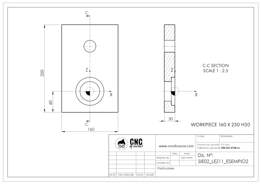
The exercise to be carried out is drawing SIE02_LEZ11_EXERCISE2.
As you saw in the lesson, the first thing to do in our Siemens program after the first comments is to define the blank.
DEFINITION OF THE BLANK FOR FACE MILL
The definition of the blank is done through the Blank function, which technically has the format of a fixed cycle despite the fact that it does not perform any operations. In fact, the Blank function is used to define the dimensions of the blank for graphics. The blank shapes can be various (Cylinder, Pipe, Block, Centered Block and Polygon). In this in-depth study, we will focus on the Block shape, which is the shape that presents some more difficulties. The Block workpiece is defined by two vertices that are opposite to each other.
Below are some examples and for each example I give you the version with the second point defined in absolute and in incremental mode. In fact, the first point that corresponds to the parameters X0 Y0 and ZA is always defined in an absolute way, thus referring to the workpiece offset. While the coordinates of the opposite point X1 Y1 and ZI can be defined either absolutely or incrementally. Absolute means that the points opposite the first must be defined relative to the workpiece offset, while incremental is defined as the path to move from the first point X0 Y0 ZA to the second point.
As also mentioned in the lesson, it is not important which of the four edges you choose as the first point of the four vertices, but the important thing is that the second point is exactly at the opposite vertex. In the examples below, the first point is always the bottom left point.
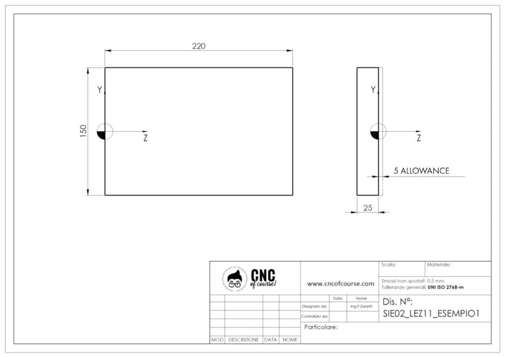
FACE MILL – CASE 1:
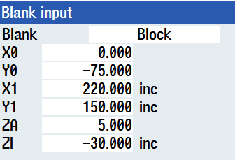
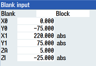
Plate of 220×150 thickness 30 mm, including 5mm allowance in Z.
Incremental version:
Absolute version:
FACE MILL – CASE 2:
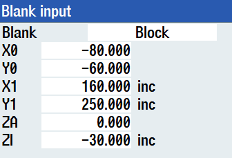
Plate 160×250 thickness 30 mm, with thickness already finished.
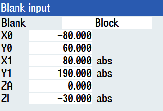
Incremental version:
Absolute version:
