Block form
Description of the Block form function
INSIGHT
PARALLELEPIPED
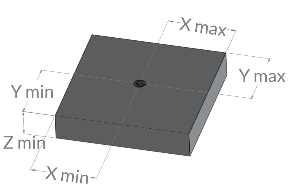
Some combinations for managing BLOK FORM are shown below.
EXAMPLE N°1
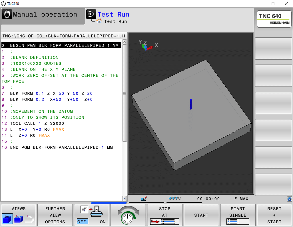
The first case repeats the example shown in the video, that is the definition of a 100X100X20 parallelepiped whose offset is positioned in the centre of the figure in relation to the X and Y axes, while the Z axis is set on the top face.
In this case, the blank is located in the X/Y plane.
In the example program, in addition to defining the blank, a tool movement is also programmed that is positioned at the zero value of all three axes, so as to give a graphic feedback to the dimensions entered.
EXAMPLE N°2
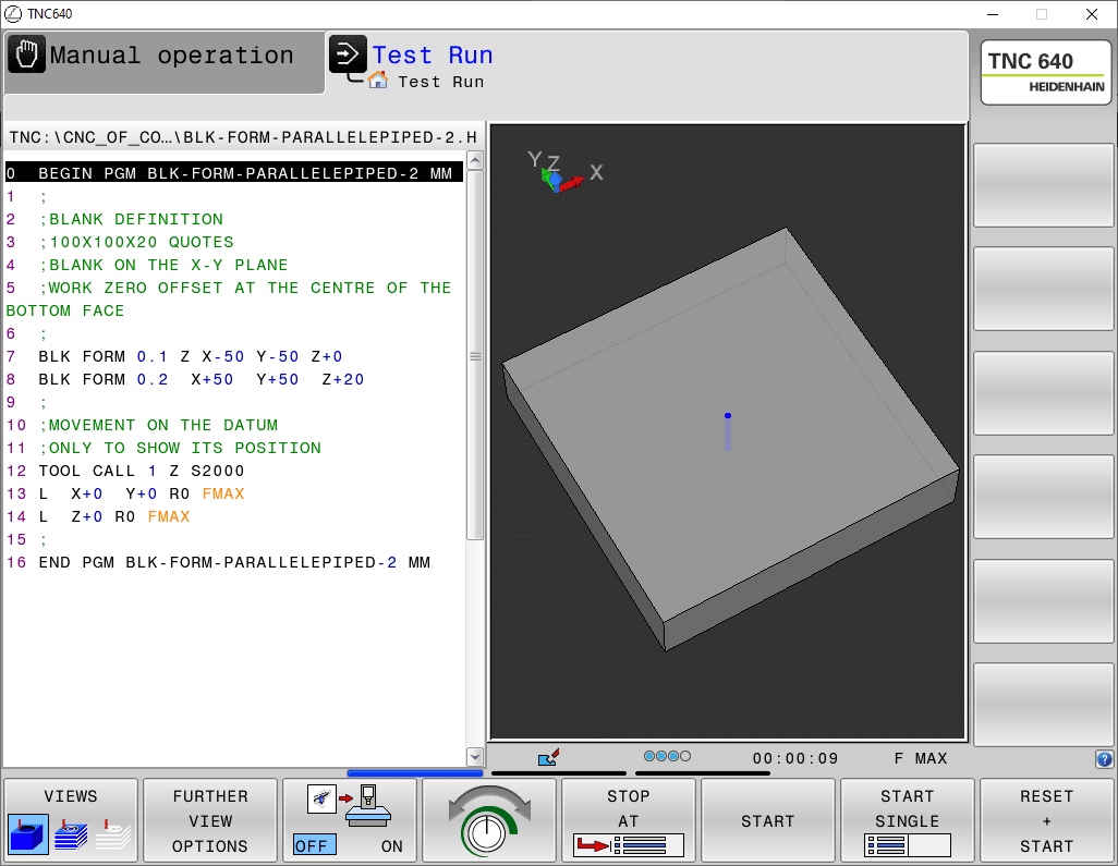
The second example shows the same 100X100X20 parallelepiped whose offset is always positioned in the centre of the figure for the X and Y axes, while the Z axis is set in the lower part.
In this case too, the blank is placed in the X/Y plane.
Here too, as in the next examples, a tool movement is programmed that will be positioned at the datum of all three axes and where it is possible to see, thanks to the transparency, the penetration of the tool inside the blank.
EXAMPLE N°3
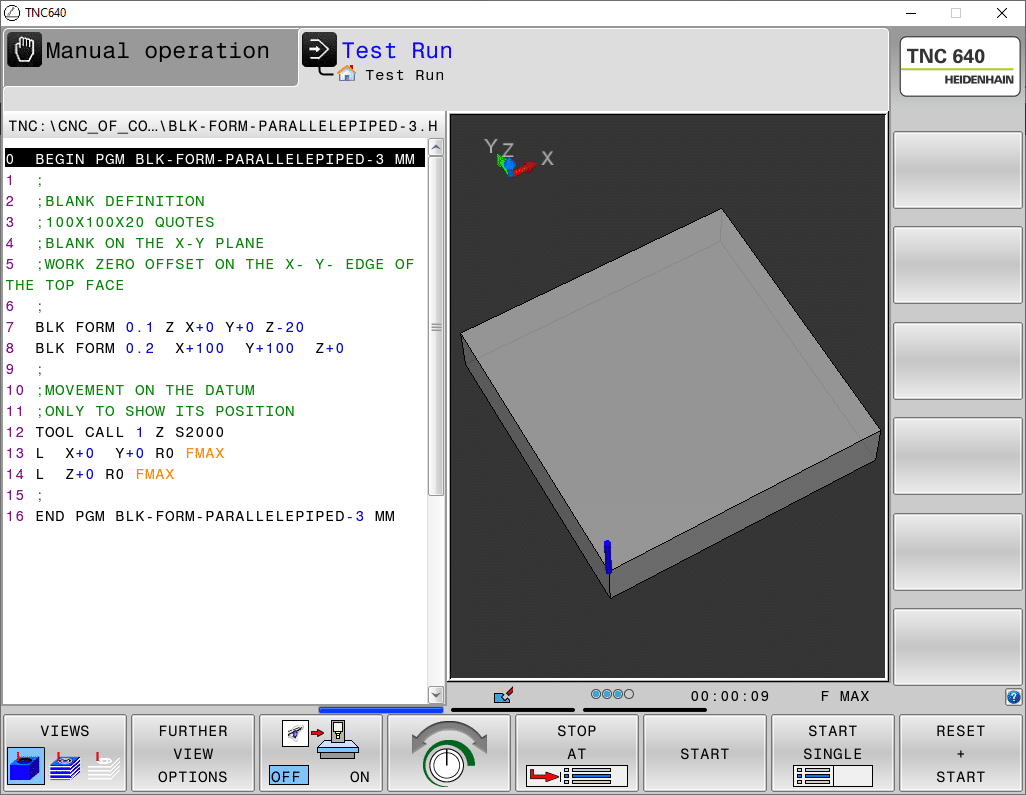
The third example shows the same parallelepiped as above, but this time the offset is on the X-Y edge and on the top face of the Z axis.
EXAMPLE N°4
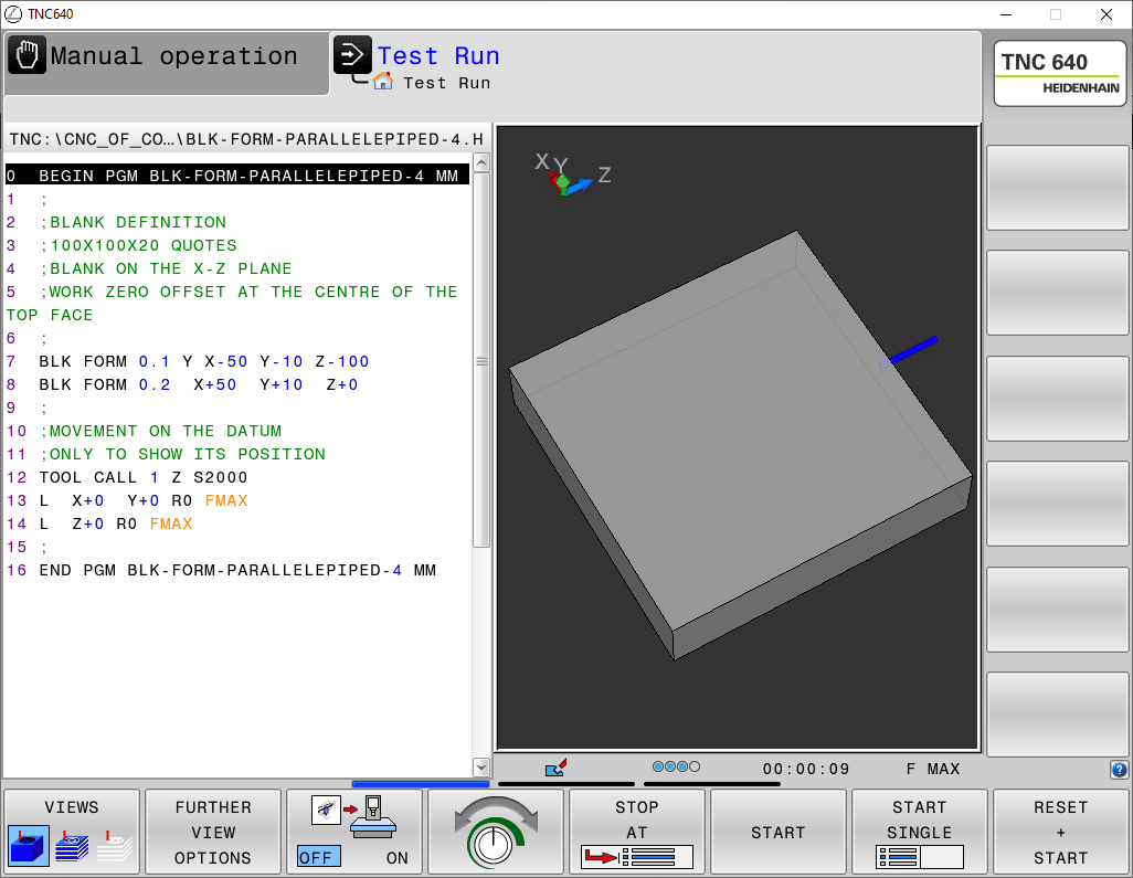
The fourth example is positioned differently: this time the figure is defined in the Z/X plane.
CYLINDER BLOCK FORM
A few more BLOK FORM examples.
This time some definitions are proposed for a cylindrical blank. Here too, different offset and orientation positions will be proposed while the cylinder keeps the same dimensions in each example (D50,H100).
EXAMPLE N°1
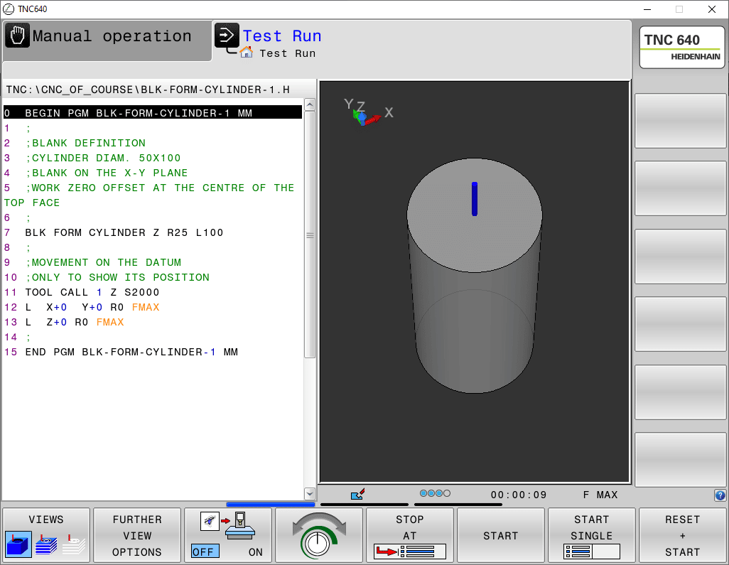
Blank positioned on X/Y plane and set to the centre of the top face.
EXAMPLE N°2
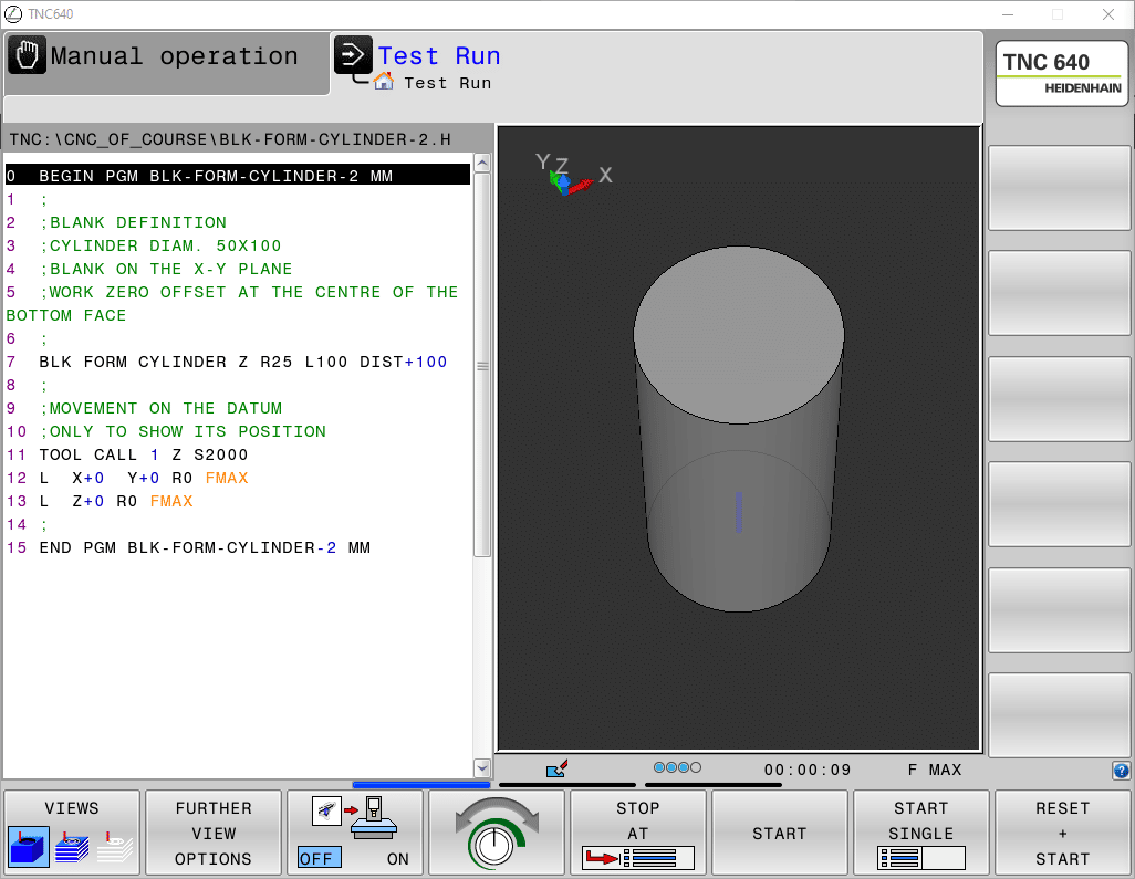
Blank positioned on X/Y plane and reset at the centre of the bottom face.
EXAMPLE N°3
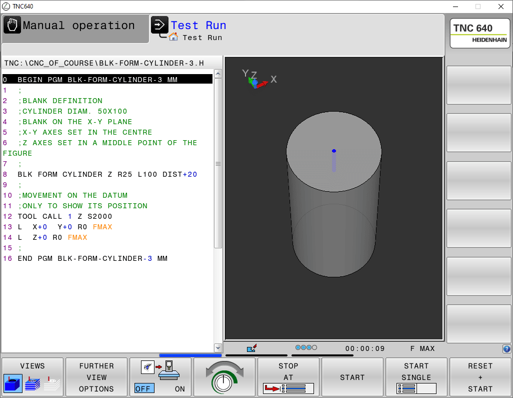
Blank positioned in the X/Y plane and Z-zero placed 20mm below the top face.
Note the intervention of the DIST field. In this case, it identifies the top face of the cylinder that is +20mm away from the Z+0 position.
EXAMPLE N°4
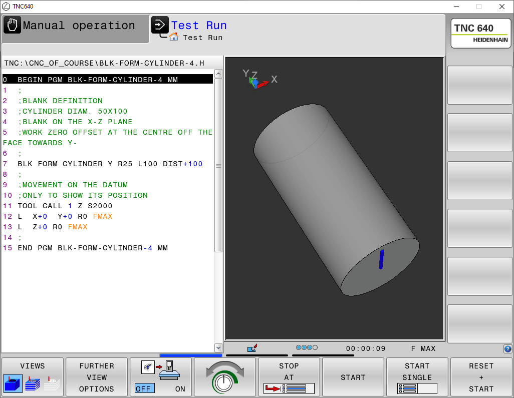
Blank oriented around the Y-axis. Work zero offset at the centre of the face towards Y-.
Due to the natural development of the cylinder towards the “minus” direction of the axis, a DIST value equal to the length was also necessary.
ROTATIONALLY SYMMETRIC BLOCK FORM
In order to use this function you need to know things that have not yet been covered in these first lessons.
However, we are proposing them so that you can return to them whenever you feel it is appropriate.
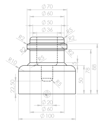
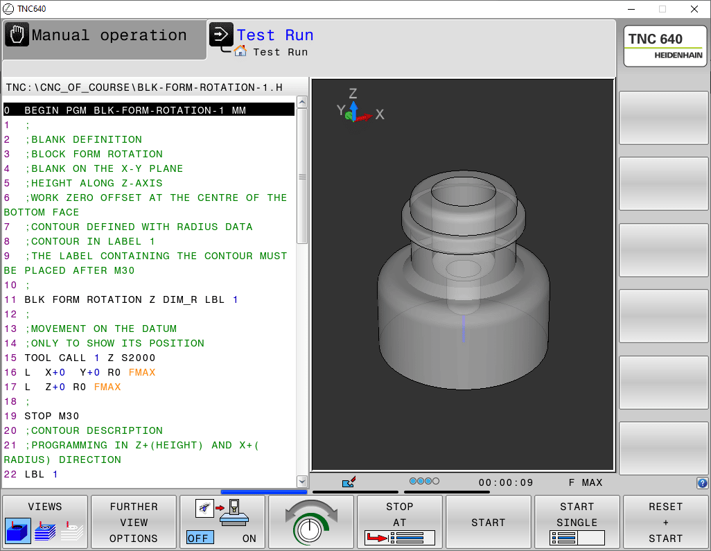
In the proposed examples, the same drawing figure is always represented but oriented along the three axes of the coordinate system.
The profile that will be developed in rotation does not have to be inserted in the “executable” part of the program. In the proposed examples it has been decided to insert the dimensions inside a sub-program placed after the function M30 (which determines the end) but alternatively it is possible to define the dimensions of the profile also in a file outside the program.
As indicated in the comment on line 21 of each program, the correct axes and directions must be programmed according to the axis around which the revolution will take place.
EXAMPLE N°1
0 BEGIN PGM BLK-FORM-ROTATION-1 MM
1 ;
2 ; BLANK DEFINITION
3 ; BLOCK FORM ROTATION
4 ; BLANK ON THE X-Y PLANE
5 ; HEIGHT ALONG Z-AXIS
6 ; WORK ZERO OFFSET AT THE CENTRE OF THE BOTTOM FACE
7 ; CONTOUR DEFINED WITH RADIUS DATA
8 ; CONTOUR IN LABEL 1
9 ; THE LABEL CONTAINING THE CONTOUR MUST BE PLACED AFTER M30
10 ;
11 BLK FORM ROTATION Z DIM_R LBL 1
12 ;
13 ; MOVEMENT ON THE DATUM
14 ; ONLY TO SHOW ITS POSITION
15 TOOL CALL 1 Z S2000
16 L X+0 Y+0 R0 FMAX
17 L Z+0 R0 FMAX
18 ;
19 STOP M30
20 ; CONTOUR DESCRIPTION
21 ; PROGRAMMING IN Z+(HEIGHT) AND X+( RADIUS) DIRECTION
22 LBL 1
23 L X+0 Z+0
24 L X+50
25 L Z+50
26 RND R10
27 L X+30
28 CHF 5
29 L Z+78
30 RND R2
31 L X+35
32 RND R2
33 L Z+88
34 RND R2
35 L X+30
36 L Z+100
37 RND R5
38 L X+18
39 L Z+50
40 RND R5
41 L X+10
42 L Z+22.5
43 RND R5
44 L X+0
45 L Z+0
46 LBL 0
47 END PGM BLK-FORM-RIVOLUZIONE-1 MM
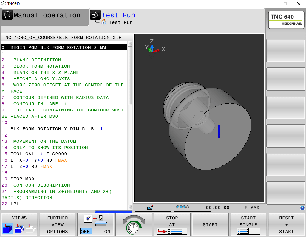
EXAMPLE N°2
0 BEGIN PGM BLK-FORM-ROTATION-2 MM
1 ;
2 ; BLANK DEFINITION
3 ; BLOCK FORM ROTATION
4 ; BLANK ON THE X-Z PLANE
5 ; HEIGHT ALONG Y-AXIS
6 ; WORK ZERO OFFSET AT THE CENTRE OF THE Y- FACE
7 ; CONTOUR DEFINED WITH RADIUS DATA
8 ; CONTOUR IN LABEL 1
9 ; THE LABEL CONTAINING THE CONTOUR MUST BE PLACED AFTER M30
10 ;
11 BLK FORM ROTATION Y DIM_R LBL 1
12 ;
13 ; MOVEMENT ON THE DATUM
14 ; ONLY TO SHOW ITS POSITION
15 TOOL CALL 1 Z S2000
16 L X+0 Y+0 R0 FMAX
17 L Z+0 R0 FMAX
18 ;
19 STOP M30
20 ; CONTOUR DESCRIPTION
21 ; PROGRAMMING IN Y+(HEIGHT) AND Z+( RADIUS) DIRECTION
22 LBL 1
23 L Z+0 Y+0
24 L Z+50
25 L Y+50
26 RND R10
27 L Z+30
28 CHF 5
29 L Y+78
30 RND R2
31 L Z+35
32 RND R2
33 L Y+88
34 RND R2
35 L Z+30
36 L Y+100
37 RND R5
38 L Z+18
39 L Y+50
40 RND R5
41 L Z+10
42 L Y+22.5
43 RND R5
44 L Z+0
45 L Y+0
46 LBL 0
47 END PGM BLK-FORM-ROTATION-2 MM
EXAMPLE N°3
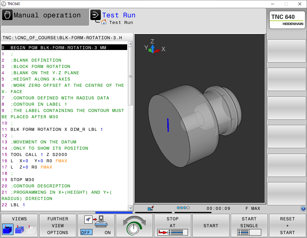
0 BEGIN PGM BLK-FORM-ROTATION-3 MM
1 ;
2 ; BLANK DEFINITION
3 ; BLOCK FORM ROTATION
4 ; BLANK ON THE Y-Z PLANE
5 ; HEIGHT ALONG X-AXIS
6 ; WORK ZERO OFFSET AT THE CENTRE OF THE X- FACE
7 ; CONTOUR DEFINED WITH RADIUS DATA
8 ; CONTOUR IN LABEL 1
9 ; THE LABEL CONTAINING THE CONTOUR MUST BE PLACED AFTER M30
10 ;
11 BLK FORM ROTATION X DIM_R LBL 1
12 ;
13 ; MOVEMENT ON THE DATUM
14 ; ONLY TO SHOW ITS POSITION
15 TOOL CALL 1 Z S2000
16 L X+0 Y+0 R0 FMAX
17 L Z+0 R0 FMAX
18 ;
19 STOP M30
20 ; CONTOUR DESCRIPTION
21 ; PROGRAMMING IN X+(HEIGHT) AND Y+( RADIUS) DIRECTION
22 LBL 1
23 L X+0 Y+0
24 L Y+50
25 L X+50
26 RND R10
27 L Y+30
28 CHF 5
29 L X+78
30 RND R2
31 L Y+35
32 RND R2
33 L X+88
34 RND R2
35 L Y+30
36 L X+100
37 RND R5
38 L Y+18
39 L X+50
40 RND R5
41 L Y+10
42 L X+22.5
43 RND R5
44 L Y+0
45 L X+0
46 LBL 0
47 END PGM BLK-FORM-ROTATION-3 MM
