Tool table and tool call function
A complete explanation of the Tool call function in Heidenhain and breakdown of the tool table management.
INSIGHT
In this lesson, we started by looking at the Heidenhain tool table and saw some of the columns that make it up.
Heidenhain tool table composition
- T: is the first column and therefore the one that identifies the tool number.
The number is the first way in which a tool is recognised and is also the most commonly used way in programming.
- NAME: the second column; it allows a name to be assigned and its main purpose is to help the operator find his way around the table, helping to recognise the tool.
Already in the development of the i530 control, and therefore also for the 640, it is possible to use the name in the programming phase.
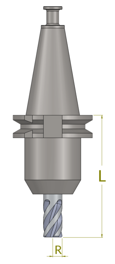
- The third column L is where the length is indicated.
In many workshops, tool presetting is done superficially and inaccurately. There are cases where the first tool is used as the “pilot” and the difference between it and the first is indicated for all the following tools; in other cases, all the lengths are referred to from a fixed value.
In other cases, all lengths are based on a fixed value. The best thing to do is to indicate the actual distance between the spindle nose and the tool nose as the length.
If the tool setting is not performed correctly, a number of problems may occur, such as loss of reference when rotating the working plane (in 5-axis machining) or the failure of anti-collision devices if your machine is equipped with them. It is therefore always a good idea to enter the correct value.
- The fourth column R is dedicated to the radius.
Here, too, you will often find values that have been modified by the operator to meet individual and specific requirements. It is always recommended to enter the nominal value of the radius and to use the appropriate fields if necessary, for example to compensate a wear.
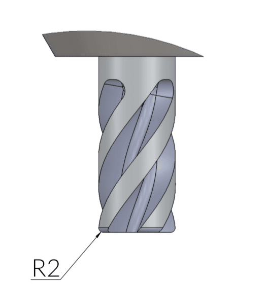
- The fifth column is called R2, which is the toroidal radius or frontal radius.
It is possible to indicate a radius between 0 (zero), in the case of a tool with a sharp-edged cutting edge, up to a toroidal radius equal to the cutter radius; in this case, the control gives a spherical profile to the tool indicated.
This information is certainly useful when graphically simulating the machining, but it is essential when machining that also takes the frontal radius into account.
- The sixth column is called DL where the letter D stands for Delta, a variation from a starting value, in this case L=length.
It is used whenever a variation from the nominal value indicated in column L is to be applied.
And when does this need to be done?
One of the most typical cases is the need to compensate for tool wear, in which case a negative value is indicated (e.g. DL-0.05) so that all machining operations are carried out as if the tool were shorter than the value indicated.
Another case might be the need to carry out machining in such a way as to leave residual material on the floor, as in the case of a roughing operation: in this case, a positive value would be indicated (e.g. DL+0.3) so that all machining would be carried out 3 tenths “higher”. The DL value is then added to or subtracted from the L value.
- The seventh column is DR and is the equivalent of the field just shown but applied to the nominal value of the radius indicated above.
A negative DR will cause the machining process to be carried out by removing extra material in addition to what has been programmed, equal to the value indicated in this column. It is as if the control considered the tool to have a smaller radius. Similarly, in the case of a roughing operation, for example, it is possible to indicate a positive value (e.g. DL+0.3) and carry out the machining with residual material equal to the value indicated.
The DR value is then added to or subtracted from the R value.
- DR2: is the eighth column and acts in the same way as the previous ones but by intervening on the R2 value.
- TL (Tool Locked): is the ninth column and is used when you need to lock a tool; for example due to a breakage, to prevent it from being taken from the magazine and set to machining.
This column can be filled in automatically if your machine has a “tool status check” system. It is blocked if it does not match the conditions set for the probing cycle.
- The tenth column is RT (Replacement Tool) and is used to indicate a replacement tool, also known as a twin.
In this case it becomes a purely programming function where, due to excessive wear, breakage or exceeding a maximum working time, the control is asked to continue machining using a replacement tool.
- Columns 11, 12 and 13 all relate to time. The CUR_TIME column counts the minutes of work done by the tool while TIME1 and TIME2 can be used to indicate a maximum duration.
The first column will stop the activity when the indicated time is reached while the second will wait for the next Tool Call at whose reading, if assigned, the replacement tool will be loaded.
There are many other fields that can be filled in and it is advisable to consult the machine manual to ensure which fields are available. It is important to remember that the fundamental fields are those contained in the first columns, while all the others depend on the characteristics of your machine, the equipment present and the complexity and the accuracy of your programming.
I also suggest the columns LCUTS=Cutting edge length, ANGLE=Max angle for linear ramp and T-ANGLE=Sharpening angle. They are closely related to some fixed cycles. LCUTS and ANGLE for pocketing cycles, T-ANGLE for drilling and centring cycles.
INDEXED TOOL
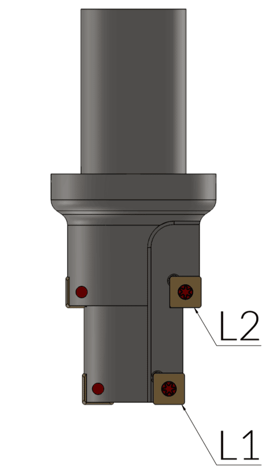
In some occasions the need to indicate more than one length or more than one radius may arise due to the geometric characteristics of the tool, as for example in the drawing shown here, or it may be necessary to modify other technological data in order to manage different ramp angles for different machining operations.
Many times this need arises from the necessity to program values that are as clear as possible and that immediately lead back to the values shown on the drawing, or to better manage tool integrity test cycles, and to this we can also add greater reliability as regards the graphic representation during the Test Run. For these reasons, it is possible to enter different geometric data for the same tool in order to meet all the operator’s requirements.
The method of creating an indexed tool is very simple.
First of all, enter in the Heidenhain tool table.
Now press the EDIT ON soft key.

Next, scrolling through the softkeys you will find a series of commands that allow you to create one or more lines in the Heidenhain tool table, delete or copy values.
Press INSERT LINE
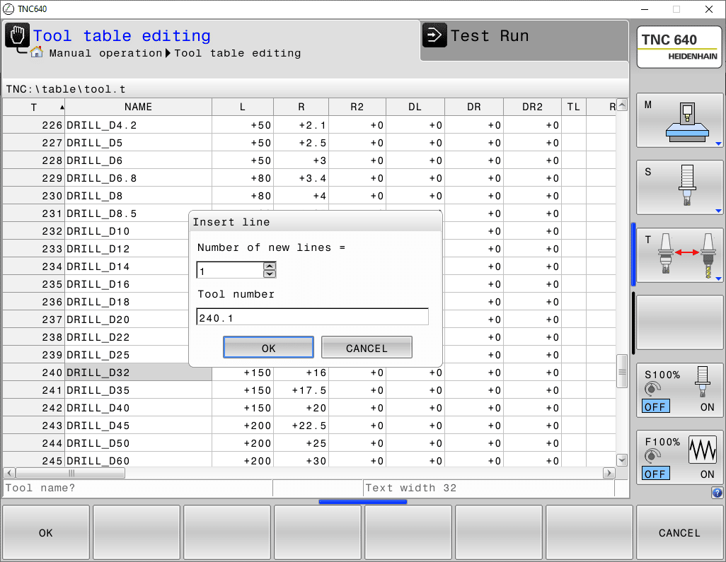
Your tool has now been created and you can enter your values.
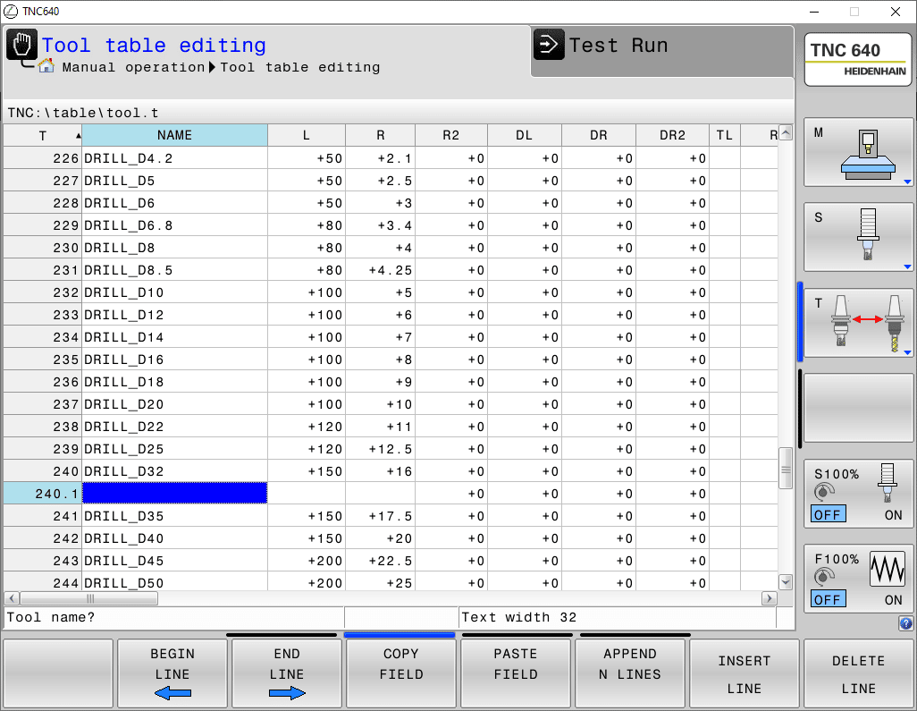
In programming, it must therefore be called as TOOL CALL 240.1 to which the call will correspond to T240 but with the data entered in line 240.1.

